• 110 - 500kV Composite-Housed Line Surge Arresters
110 - 500kV Composite-Housed Line Surge Arresters
discuss personally
Model
YH10CX1-288/755
Basic info
Brand ROCKWILL
Model NO. 110 - 500kV Composite-Housed Line Surge Arresters
Rated voltage 220kV
Rated frequency 50/60Hz
Series YH10CX
Product Detail

Description

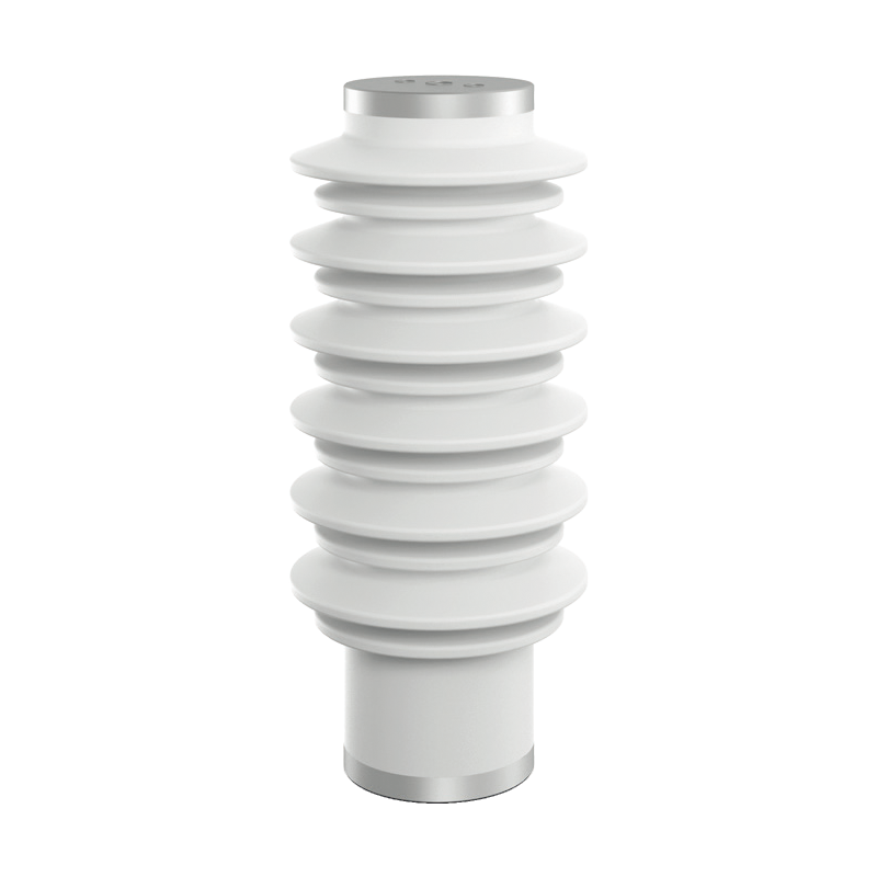
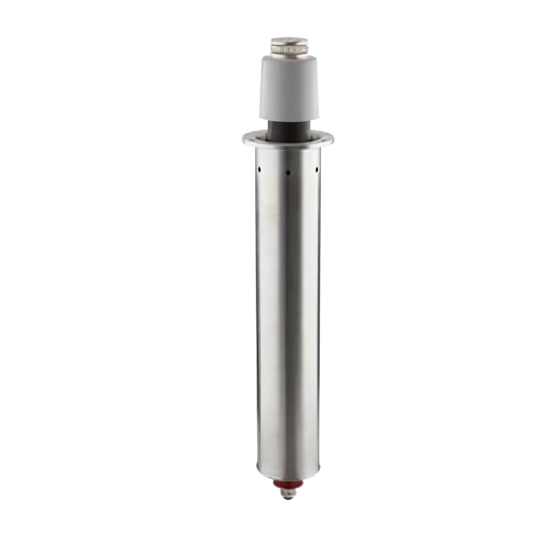
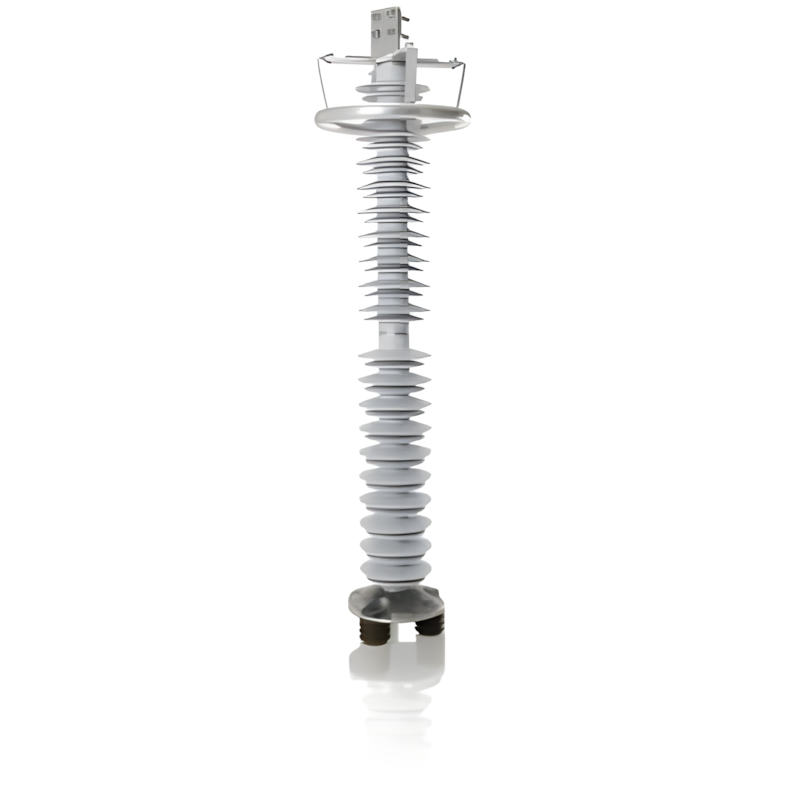
110 - 500kV Composite-Housed Line Surge Arresters are specialized protective devices designed for high-voltage transmission lines operating within the 110kV to 500kV range. Encased in durable composite housings (typically silicone rubber), they integrate advanced metal oxide varistor (MOV) technology. Installed directly on transmission lines, these arresters serve as a critical defense against overvoltages caused by lightning strikes, switching transients, and other electrical disturbances. By rapidly diverting surge currents to the ground and clamping voltage levels to safe thresholds, they prevent damage to line components, minimize power outages, and ensure the stable and efficient operation of 110 - 500kV transmission networks.

Features

Broad Voltage CompatibilityTailored to cover the 110kV to 500kV range, these arresters are engineered to match the specific voltage requirements of high-voltage transmission lines. This versatility allows them to provide consistent and reliable protection across various segments of the power grid within this voltage spectrum.

Durable Composite HousingThe composite (silicone rubber) housing offers exceptional performance. It exhibits strong resistance to environmental factors such as UV radiation, extreme temperatures, moisture, and pollution, ensuring long-term stability even in harsh outdoor conditions. Additionally, its lightweight nature simplifies installation and reduces the load on transmission line structures.

High-Performance MOVsEquipped with high-quality metal oxide varistors, these arresters feature excellent nonlinear resistance characteristics. During overvoltage events, the MOVs quickly conduct large surge currents, effectively limiting voltage spikes. In normal operation, they maintain a high-resistance state, minimizing leakage current and energy loss.
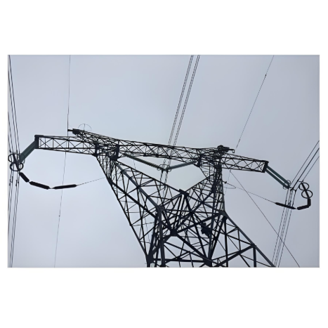
Line-Specific DesignDesigned specifically for integration with transmission lines, they have a compact and streamlined structure that fits seamlessly into line configurations. This design ensures minimal impact on line performance while providing optimal protection, making them suitable for both overhead and certain underground transmission line setups.

Superior Surge HandlingCapable of withstanding high impulse currents generated by severe lightning strikes and switching surges. Their robust surge handling capacity ensures that even under extreme electrical disturbances, the arresters can effectively mitigate the impact, safeguarding line insulators, conductors, and other critical components.

Low Maintenance RequirementsThe composite housing is resistant to aging and corrosion, reducing the need for frequent maintenance. The MOVs are designed for long-term reliability, with stable performance over extended periods, minimizing downtime and operational costs associated with upkeep.

Compliance with StandardsAdheres to international industry standards such as IEC 60099 - 4 and ANSI/IEEE C62.11, ensuring compatibility with global transmission systems. Compliance with these standards guarantees that the arresters meet strict safety and performance criteria, providing confidence in their operational effectiveness.

Enhanced Grid Reliability:By preventing line tripping and equipment damage caused by overvoltages, these arresters contribute significantly to the overall reliability of the power grid. They help maintain continuous power transmission, reducing the frequency and duration of outages, which is crucial for meeting the demands of industrial, commercial, and residential users.

Model 

Arrester

System

Arrester Continuous Operation

DC 1mA

Switching Impulse

Nominal Impulse

Steep - Front Impulse

2ms Square Wave

Nominal

Rated Voltage

Nominal Voltage

Operating Voltage

Reference Voltage

Voltage Residual (Switching Impulse)

Voltage Residual (Nominal Impulse)

Current Residual Voltage

Current - Withstand Capacity

Creepage Distance

kV

kV

kV

kV

kV

kV

kV

A

mm

(RMS Value)

(RMS Value)

(RMS Value)

Not Less Than

Not Greater Than

Not Greater Than

Not Greater Than

20 Times


(Peak Value

(Peak Value

(Peak Value

(Peak Value


YH10CX1-102/296

102

110

81.6

148


296


600

5438

YH10CX1-204/592

204

220

159

296


592


600

10600

YH20CX1-396/1050

396

500

297

561


1050


1200

23310

YH10CX1-204/592K

204

220

159

296


592


600

5400

YH10CX1-288/755

220

330

216

408


755


600

16100

Know your supplier
ROCKWILL
Rockwill Electric Group Global Manufacturer of High voltage and medium-voltage power equipment and smart grid solutions. Headquartered in Wenzhou, China. Serving 100+ countries with quality, innovation, and trust. What We Offer: • HV-MV switchgear (VCB, SF₆ circuit breakers, RMU, GIS) • Distribution transformers and substations • Smart grid and monitoring systems • Solar, wind, EV charging, and energy storage solutions • EPC turnkey power projects Certified: ISO 9001 / ISO 14001 / ISO 45001
Main Categories
High Voltage Electrical Apparatus
Business Type
Design/Manufacture/Sales
Highest Annual Export (USD)
$150,000,000
Professional Experience
16 years
Workplace
108000m²m²
占位
占位
Related Products
Related Knowledges
Analysis of Abnormal Causes of High-Voltage Cable Grounding Circulation and Typical Cases
I. Introduction to Cable Grounding Loop CurrentCables rated 110 kV and above use a single-core structure. The alternating magnetic field generated by the operating current induces a voltage on the metallic sheath. If the sheath forms a closed circuit through the earth, a grounding loop current will flow on the metallic sheath. Excessive grounding loop current (loop current exceeding 50 A, more than 20% of the load current, or a ratio of maximum-to-minimum phase current greater than 3) not only a
Felix Spark
09/03/2025
Considerations and Recommendations for Flame-Retardant Selection of High-Voltage Cables
1.Flame-Retardant Cable Classification StandardsThe flame-retardant standard system is divided into two main categories. The first category follows the "Classification of Burning Behavior for Electric and Optical Fiber Cables" GB 31247. Cables complying with this standard system are widely used in densely populated areas such as high-speed railways and subways. This standard imposes strict requirements on parameters such as smoke density, heat release, and total smoke production, and cables typi
James
09/03/2025
Repair of high-voltage cable metallic sheaths
I. Functions of Metallic Sheaths and Necessity of RepairThe metallic sheath of high-voltage cables is a metal shielding structure laid outside the insulation layer, including types such as lead sheaths, aluminum sheaths, and steel wire armor. Its core functions include mechanical protection (resisting external impact and compression), electrochemical corrosion protection (isolating moisture and soil pollutants), electromagnetic shielding (reducing electromagnetic interference to the environment)
Felix Spark
09/03/2025
What factors need to be considered when designing a transformer?
Transformer design is a complex process that requires consideration of multiple factors to ensure safe and efficient operation. In addition, compliance with international and local regulations is essential to guarantee that transformers meet safety and performance standards. Below are key factors to consider in transformer design and the relevant regulations to follow:Transformer Design Factors: Voltage and Frequency: Determine the input and output voltage levels and the operating frequency. The
Vziman
09/02/2025
What failure modes are possible in a transformer? How to identify and fix these failures?
Transformers are critical components in power systems, and various failure modes can affect their operation. Timely identification and resolution of these failure modes are essential to prevent costly downtime and ensure system reliability. Below are some common transformer failure modes, along with methods to identify and address them: Insulation FailureIdentification: Insulation failure leads to decreased insulation resistance, which can be detected through insulation resistance testing (megge
Edwiin
09/02/2025
A hybrid DC circuit breaker
Most DC molded-case circuit breakers use natural air arc extinction, and there are typically two arc extinguishing methods: one is conventional opening and closing, where the contacts axially stretch the arc, while the conductive circuit generates a magnetic field that bends and elongates the arc, pulling it lengthwise perpendicular to the arc axis. This not only increases the arc length but also induces lateral motion, enabling air cooling to achieve arc extinction.The other method involves the
Echo
09/02/2025
×
Inquiry
Download
IEE-Business is dedicated to serving the personnel in the global power industry.
Join IEE-Business, not only can you discover power equipment and power knowledge, but also canhnd like - minded friends!